Jon Hilty
Simple Nixie Clock
After having the parts sit around for months, I finally went ahead and built a nixie clock. A Nixie Tube is a neon-filled glass tube that glows when a high voltage is passed through it. Although it varies by tube type, there are usually 10 cathodes that correspond to digits 0 - 9. They produce very little heat and can run for decades.
To make a nixie clock you're going to need a few things:
1. Nixie Tubes. My clock uses 6 IN-14s. ~$20
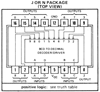
2. High Voltage drivers. These chips will channel the 5v binary output from the Arduino into a high voltage signal to the tube. Use the russian K155ID1 or the American 74141 chips. ~$10
3. Current limiting resistors, to prevent current going over 2.5mA per tube. This prevents unnecessary damage to the tube itself, as well as protecting the driver. 22kohm is a good place to start, but I'd recommend getting a variety pack. < $1
4. An Arduino Mega. ~$15
5. High Voltage supply. There are plenty of plans to build your own out there, but I was lazy and they are fairly cheap. ~$20
6. An RTC (real time clock) module -- A special add-on for the Arduino, since the Arduino itself is bad at keeping accurate time. I used (and the code is designed for) a DS3231. ~$2
7. 12V Arduino power supply (will also be used to power the nixies) ~$3
Total cost for the Nixie core components = ~ $70

For my first build I decided AGAINST multiplexing, instead opting for a very simple, straightforward project. Not multiplexing means requiring six Nixie drivers (one for each tube), and each of those requiring 4 binary inputs -- a total of 24 digital outputs. An Arduino Uno only has 14 I/O pins, meaning we'll need to upgrade to its bigger brother, the Arduino Mega.
This is great and all, but how does this work together?
I'm a paragraph. Click here to add your own text and edit me. I’m a great place for you to tell a story and let your users know a little more about you.
See the expertly made diagram on the right. A "binary" number is generated from four Arduino pins and fed into the nixie driver, where "A" is the most significant digit and "D" is the least. Giving the driver a value such as "3" (0011 in binary) will open up a channel through the digit connected to "3". Now a circuit is complete, and the +170V can flow through the anode pin to the "3" shaped cathode, causing the neon around it to glow.


IN-14 Nixie Pinout
Nixie Driver Pinout
Basic Nixie circuit setup
Let's get this all hooked up!
Let's start with the 6th digit (from left to right), the second's lowest digit. It will always be changing, so it will make it easy to see if everything is wired up right.
Hook up the DS3231 clock: Connect SDA on the clock to Pin 20, and SDL to Pin 21. Connect VCC to the +5V output from the Arduino and GND to GND.
Connect the nixie: Hook up the output pins to their respective cathode numbers on the nixie tube (e.g. Cathode "1" goes to pin 15 on the driver). Connect the anode pin to the +170V output from the nixie power supply (don't forget that 22kohm resistor!)
Connect the driver to the Arduino: Pins 6, 7, 8, and 9 on the Arduino will be the inputs A, B, C, and D for the driver. Connect the +5V from the Arduino to Pin 5 on the driver, and Arduino GND to Pin 12.
Download the program: My program can be found here. Download the program onto the Arduino. Power up the arduino and connect the nixie power supply to a 12V source.
When you're finished, you'll get something like this:
Wire up the rest of the digits

The binary digit pins for the rest of the drivers are as follows (left to right)
Hours Digit 1: 30, 31, 32, 33
Hours Digit 2: 34, 36, 37, 35
Minutes Digit 1: 25, 24, 23 ,22
Minutes Digit 2: 26, 28, 27, 29
Seconds Digit 1: 2, 3, 4, 5
These pin numbers can be changed at any time by modifying the "digit" arrays at the beginning of the Arduino program. I "swapped" a few numbers because I had incorrectly hooked up the wires and didn't feel like correcting them physically.
All the anodes can be wired individually to the 170V supply or be wired from one anode to another. The same goes for the +5V and GND for the driver chips. Make sure you keep the high voltage well insulated, it could accidentally short through a driver chip and fry it (I did that in one instance, it was quite a pain to rewire).
Right now the time is set by entering the information into line 35 in the program:
setDS3231time(15,34,21,4,11,3,15);
Simply modify the parameters to the current time and download the program to the Arduino. Now, this means every time the arduino resets (loses power, reset button is pressed) it will set the time to whatever is defined in line 35, which is wrong if you've had it running for more than a second. To fix this, after you have first set the clock, comment out the line like this:
//setDS3231time(15,34,21,4,11,3,15);
Now the RTC will retain the time as long as its battery lives!
You will notice that once per minute, all the digits rapidly cycle. This isn't a bug, it's a feature -- according to this, nixie tubes need their digits cycled periodically to help extend their life (digits stuck on for a long time will begin to "burn" out and sputter -- not good!).